Previously we looked at the basics of prosthetic alignment and briefly described the process of finding an individual alignment. In Part 2, we will take a closer look at the individual alignment of the socket.
The topic we are going to discuss is quite difficult to explain because, even among professionals, alignment principles are still debated. The information provided in this article is simplified and given for familiarisation purposes only. As always, we strongly recommend that you discuss your personal situation with your prosthetist.
We would highly recommend that before continuing with this article that you read Part 1. The Basics.
To simplify our explanation, we will look at each of the parts that make up a prosthetic leg and explain what effects alignment has on them. In this article we will focus on the prosthetic socket and in Prosthetic Alignment: Part3, we will discuss knee units, prosthetic feet and mentally assemble the prosthesis to understand how the whole artificial leg is affected by alignment.
Socket. Static alignment.
In part 1, we briefly mentioned the use of reference lines drawn on the prosthetic check socket but did not fully explain their significance. These lines are vital to finding the best place to position the prosthetic components under the socket.
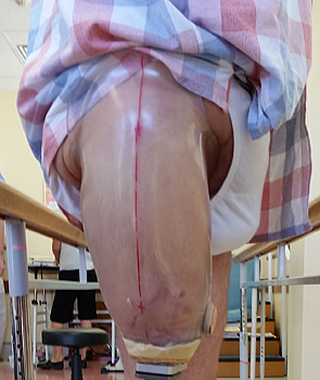
The picture above shows a reference line drawn on the check socket.
The prosthetic socket connects to the rest of the artificial leg by means of a socket adapter. In general, the positioning of this adapter should coincide with the point where the frontal and sagital planes intersect on the bottom of the socket.
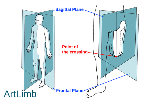
The picture above shows the frontal and sagittal planes projected on the human body and a trans-femoral socket highlighting where the planes cross.
If the socket adapter is located in the correct position, the amputee should be able to stand and maintain balance naturally without excessive effort.
To illustrate this, imagine the amputee having donned the socket, without any other components attached and standing on a point support connected to the socket adapter. If the adapter was incorrectly placed for the individual, we will observe deviations of the socket and body, or excessive muscle tension (i.e. the amputee would not be able to maintain relaxed posture).
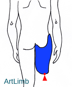
The picture above shows an appropriate individual position of the socket adapter in frontal plane with the socket in equilibrium. The point support (where the socket adapter should be placed) is depicted in the shape of a red triangle. A red dot is used to indicate where two planes (frontal and sagittal) intersect on the bottom of the socket.

The picture above shows a situation where the socket adaptor is positioned too far medially in the frontal plane. The socket is not in equilibrium and tends to tilt laterally due to rotating forces.
As before, the point support (where the socket adapter has been placed) is depicted in the shape of a red triangle. A red dot is used to indicate where two planes (frontal and sagittal) intersect on the bottom of the socket in an equilibriated position.
As we mentioned in Part 1, prosthetic alignment is a very individual process. An appropriate alignment must maintain the physiological positions of the upper joints, whilst accommodating for joint contractures, body mass distribution, etc.

The picture above shows an appropriate individual position of the socket adapter in the sagittal plane (this socket is in equilibrium)

The picture above shows the position of the socket adapter is located too far forward in the sagittal plane (this socket is not in equilibrium and tends to tilt backwards).

The picture above shows the position of the socket adapter found without taking into account a contracture of the hip joint in the sagittal plane. In this case, the amputee has to strain their back (depicted by red arrow) to maintain a vertical position. Previously this situation was illustrated with photos in Part 1. The Basics, chapter “Static Alignment”.
The socket adaptor we keep refering to is the first modular prosthetic component attached to the socket and allows us to assemble the rest of the leg in a particular direction. To do this adaptors have their own assembling direction.

The picture above shows two different socket adapters. The red arrows indicate the assembly directions that are important to be in the parallel position to the both frontal and sagittal planes.

The pictures above shows an appropriate individual position of the socket adapter in frontal plane. However, the right figure shows the situation where the socket adaptor assembling direction is not parallel to the frontal plane. This socket is not in equilibrium and tends to tilt laterally due to the angle between the socket and the rest of the prosthetsis.
There is no point support illustrated because in this case the socket is angularly connected to the rest of the artificial leg. A red dot is used to indicate where two planes (frontal and sagittal) intersect on the bottom of the socket in an equilibriated position.
Socket. Dinamic alignment.
When the prosthesis is assembled, the alignment of the socket can be adjusted using adjustable adapters during the check walk. The main method of adjustment is by observing the amputee walking and correcting deviations of body segments and prosthetic components (tilts, pathological movements, excessive muscle tensions, etc).
Very often, due to the individual’s gait pattern, the final prosthetic alignment may differ from the initially set static alignment.
Conclusion
The socket is the most individual part of the prosthetic limb and transfers all forces between the body and the prosthesis. Without an appropriate individual alignment of the socket in relation to the amputee’s body, these forces may negatively impact on the human/prosthetic system and may result in gait deviations, an energy in-efficient walk, or be potentially dangerous for the muscular-skeletal system.
Read Alignment: Part1. The Basics ⇒
Oi
Very good
You aer v.goot
I LIKE THE INFORMATION THAT YOU SHOWED SET FOR HIP TYPE LEG. I HAVE BEEN A USER FOR OVER 50 YEARS. THANK YOU8. AND IF ANYONE WITH THE SAME TYPE LET LETT ME KNOW. MAYBE I CAN HELP YOU.