Previously, in Part 1 we looked at the basics of prosthetic alignment and briefly described the process of finding an individual alignment.
In Part 2, we looked closer at how the alignment of a prosthetic socket, the most individual part of the artificial limb, is found and adjusted.
In part 3 we will start to look at prosthetic components beginning with prosthetic feet. Specifically we will be discussing how their alignment influence the prosthesis and the body.
The information provided in this article is simplified and given for familiarisation purposes only. As always, we strongly recommend that you discuss your personal situation with your prosthetist.
We would highly recommend that before continuing with this article that you read Part 1. The Basics and Part 2. The Socket.
The prosthetic foot transfers all the forces between the ground and the prosthesis making correct alignment of this component vital for a smooth and natural gait.
All prosthetic feet have a manufacturers recommended alignment reference point. This reference point is used in combination with the alignment we have already found for the socket to provide a safe initial prosthetic setup. An incorrect initial position can lead to inappropriate force transfer from the ground to the prosthesis which will be immediately felt by the wearer.
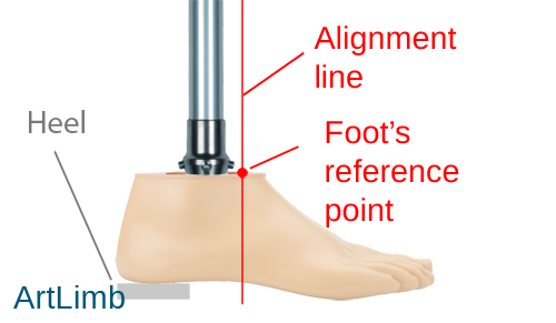
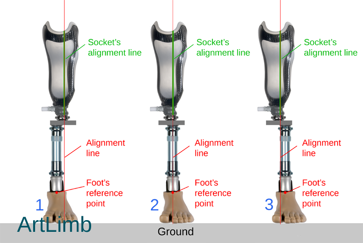
The photo above shows the reference point on a prosthetic foot as a red dot. The vertical alignment lines found from the prosthetic socket are shown to pass through this point.
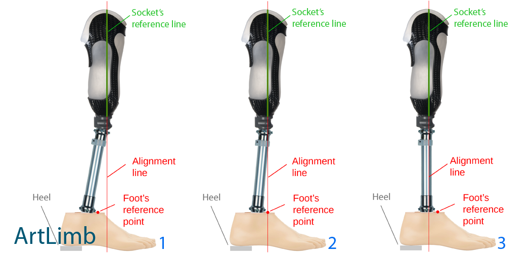
To show this in practice, below are a collection of pictures illustrating what an incorrect and appropriate starting alignment can look like and what the amputee may feel in each situation.

The picture above demonstrates three different positions of the foot in the sagittal plane (side on view).
Figure 1 shows an alignment line which falls too far forward from the reference point of the foot. In this case the amputee will not feel support from the toe when standing and perceive the toe as too soft when walking.
Figure 2 shows a correctly aligned foot.
Figure 3 shows an alignment line which falls too far behind. In this case the amputee will not feel support from the heel when standing and perceive the toe as too stiff when walking.
The picture above demonstrates the same three positions as depicted before, but the alignment has been build up by means of angular changes.
It is visible that the mutual positions of the foot, socket and alignment line have remained the same (compared to the previous picture), but angles and the position of the connecting tube have changed. The reason we highlight this is to explain that it is the relative position of the functional parts (socket, foot, knee, etc) that are important to an appropriate alignment. The ways they are connected can differ but the functionality of the whole prosthesis will be similar.
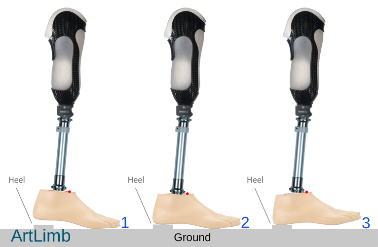
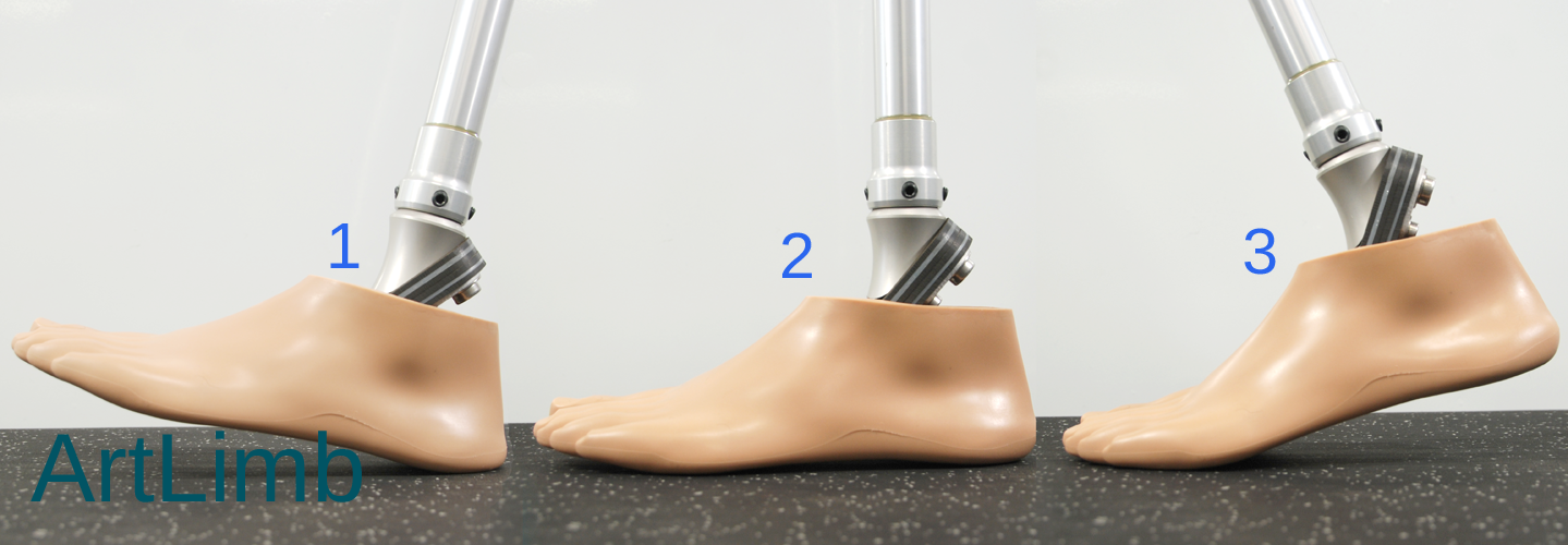
The picture above demonstrates three different angled positions of the foot in the sagital plane.
Figure 1 shows a position where the foot is too plantarflexed (toe pointed down). In this case the prosthesis will tilt backwards and the amputee will have to make additional effort to maintain a vertical position. During walking, perceptions can vary. It may feel like the toe is too stiff and difficult to progress over.
Figure 2 shows a correctly aligned foot.
Figure 3 shows a position where the foot is too dorsiflexed (toe pointed up). In this case the prosthesis will tilt forward. In most cases, the amputee will feel like they are walking down hill.
The picture above demonstrates three different positions of the foot in the frontal plane.
Figure 1 shows the foot aligned too far medially. This results is the prosthesis tilting laterally.
Figure 2 shows a correctly aligned foot
Figure 3 shows a foot aligned too far laterally. This results with the prosthesis tilting medially.

The picture above demonstrates two different incorrect angled positions in the frontal plane.
It is visible that if the foot is not horizontal to the ground it leads to a tilt of the whole prosthesis. During walking, depending on the amputees physical condition, they may either feel this deviation or feel like they are walking on the edge of their foot.
In the previous articles we have discussed the sagital and frontal planes. To help us explain the alignment of prosthetic feet fully, we will need to introduce the third plane which is called the horizontal or transverse plane.
![]()
The picture above shows the transverse (horizontal) plane projected on the human body and foot. The position of the foot in this plane in prosthetics is usually referred to as rotation.

The picture above demonstrates the initial placement of the foot (figure 1) and its externally rotated position (figure 2).
If the prosthetic foot is not placed in the correct rotational position, the amputee may feel instabilities as they progress over the prosthetic foot when walking. The artificial foot is designed to have dynamically changing contact with the ground which allows the amputee to maintain the direction they are walking in. This is achieved by the rollover characteristics of the foot which can be broken down into three distinct stages.
The picture above demonstrates the 3 stages when the prosthetic foot has contact with the ground.
Figure 1 shows Initial contact – When the heel meets the ground during walking.
Figure 2 shows Full contact – The next stage when the entire sole of the foot has contact with the ground.
Figure 3 shows Toe loading – This is the last stage when only the toe has contact with the ground.
Following each other, these three stages combine to become rollover.
The video above demonstrates rollover in motion
Incorrect rotation of the foot leads to inappropriate dynamic forces transferring from the ground to the prosthesis. Every foot is designed to work in a very specific position in terms of rotation. It is important to note that sometimes this position does not match that of the opposite side (amputees remaining foot).
For example, if the artificial foot is overly externally rotated (rotated to the outside), the line of progression of the amputees body during walking will not coincide with the active plane of the foot. This will result in the prosthesis to slightly tilt laterally (outwards) during initial contact and tilt medially (inwards) during toe load. This phenomenon will be felt and seen only when walking. When standing, the amputee will not perceive this issue.

The picture above demonstrates overly externally rotated (rotated to the outside) foot, the line of progression of the amputees body and the active plane of the foot.
As we mentioned before, this article tries to explain the principles of foot alignment in a simplified way. It is worth noting that the position of the foot in each of the three planes will have a significant impact on the gait pattern of the amputee.
In the next part of our alignment articles we will look at how the alignment of prosthetic knee units can further impact on the functional characteristics of the whole prosthesis.
Read Alignment: Part1. The Basics ⇒
Read Alignment: Part2. The Socket ⇒